Automated testing, designed around your engineers.
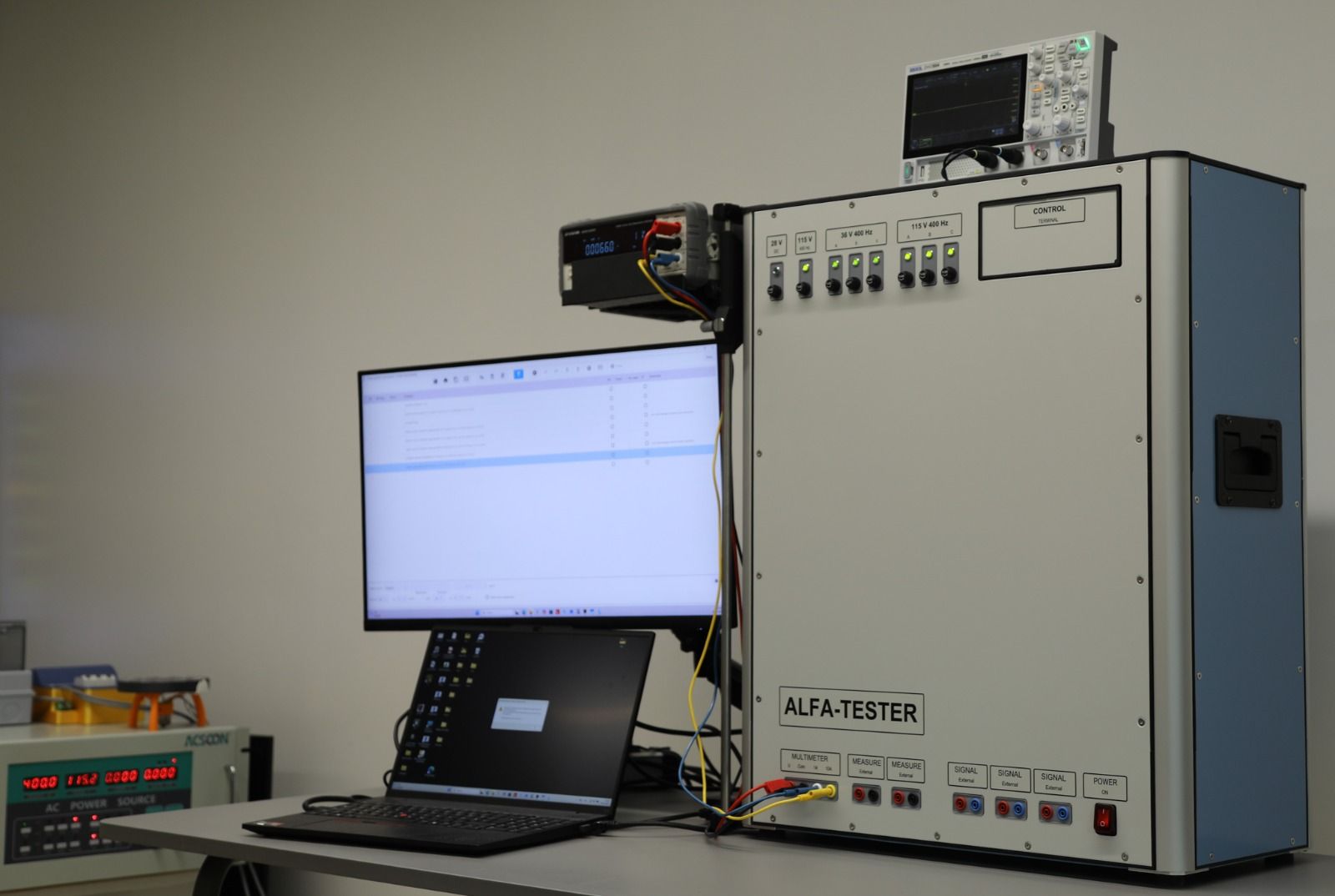
ALFA-TESTER is a universal system for automated testing of electrical and electronic equipment in aviation and other high-reliability industries. Engineers write the test program. The tester generates the harness wiring diagram, then applies the signals, switches, measures and writes the test report on its own.
Meet us at the Aerospace Test & Development Show 2026
29–30 September, Hall 7, MEETT, Toulouse, France. Open 10am to 5pm.
Write a test program, not a new adapter.
The usual way
Traditional automated test systems often need a dedicated adapter for each unit, so every change to a unit turns into a costly, time-consuming adapter change.
With ALFA-TESTER
No switching or interface adapters. Testing a new device comes down to writing the test program and making a cable harness, and the harness wiring diagram is generated while the program is written.
Test programs that read like a technical document.
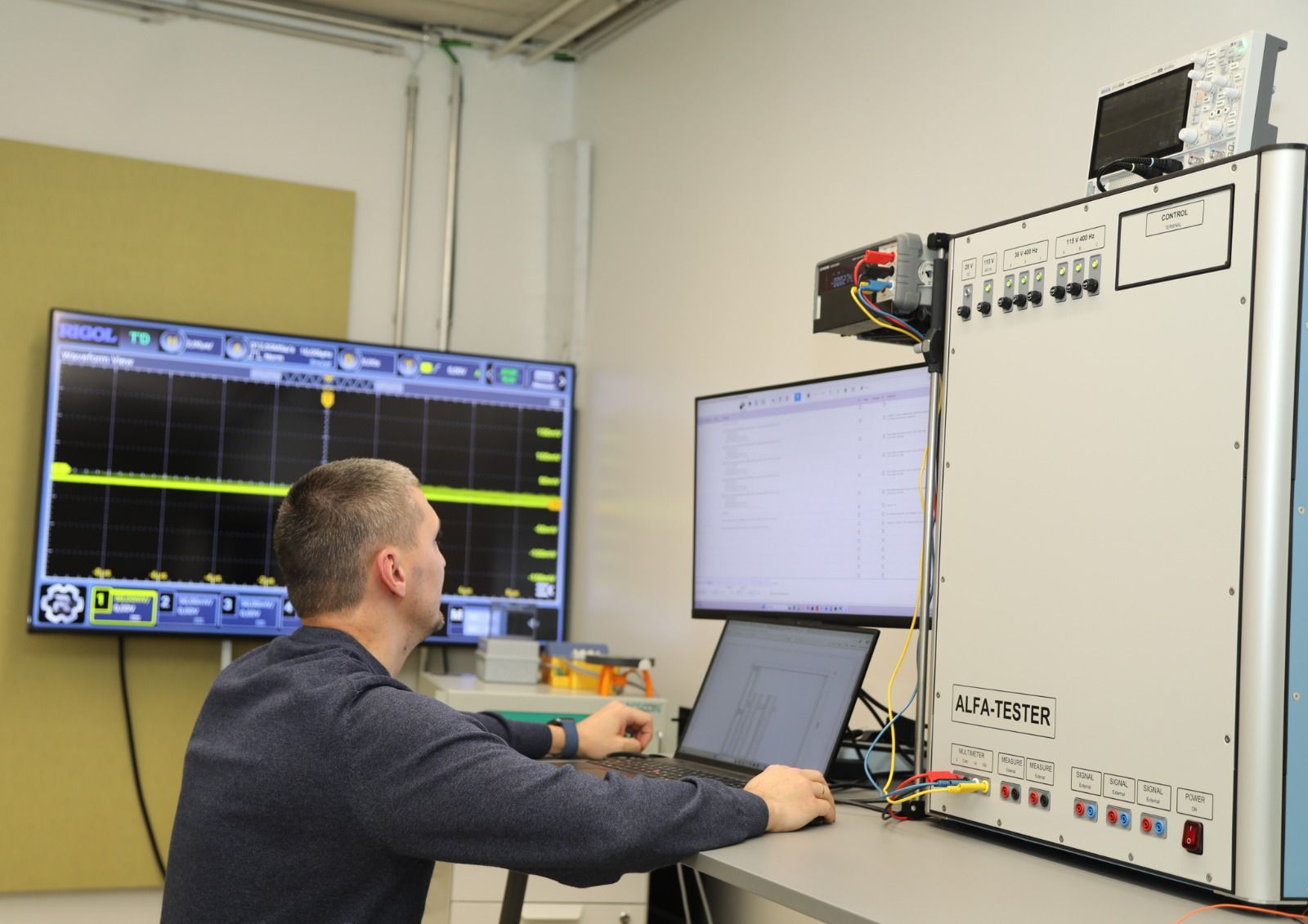
The program author picks a command from a menu and completes it with a name, the tolerances and the connector and pin designations. Commands are named after what they physically do, so engineers and technicians write test programs themselves, the way they write test procedures, with no programmer involved.
- Apply input voltage Uin = (6.2 ± 0.05) V to connector 2C, pin 14 and connector 2C, pin 22
- Measure bias current = (12 ± 0.25) mA on connector 2V, pin 17 and connector 2V, pin 18
During a test the program runs on screen with the current command highlighted, so the operator can follow every step, analyse the run and act quickly when something fails.
Signals, switching and measurement in one unit.
One 640 × 740 × 300 mm monobloc, with six 50-pin connectors on the rear panel for the unit under test.
Stimulus signals
- Fixed DC: 28 V, 12 V, 5 V
- Fixed AC: 36 V, 115 V, 200 V at 400 Hz
- Adjustable DC and AC (50 Hz, 400 Hz) voltage and current sources
- Resistances
- Pulse signals, sine and triangle waveforms
- Angle signals
Measurement
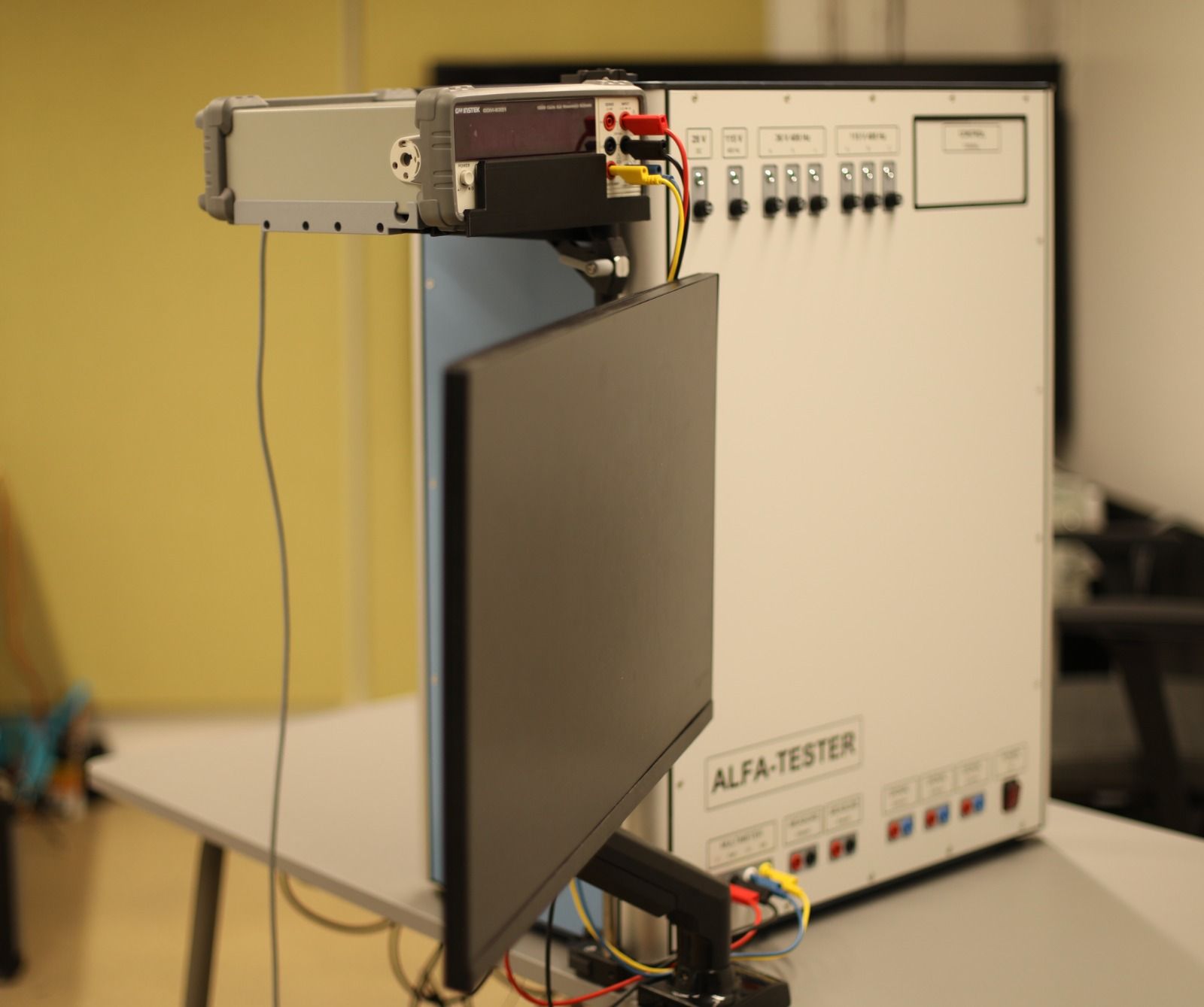
A high-precision GW Instek meter sits on a platform that swivels and slides on a post, keeping the display in view and its controls locked during a test. Pulse amplitude, duty cycle and angle are measured automatically too.
Switching
Up to three external signal sources and two measuring instruments can be connected to any pins of the unit under test at the same time.
Tests other automated systems rarely handle.
ALFA-TESTER runs any test that applies and measures voltage, current, resistance or pulse signals. It also automates these:
Relay and contact assemblies
Pick-up and drop-out voltages, contact condition at low-level and rated currents, insulation resistance.
Onboard control panels
Controls switched on and off in sequence from on-screen prompts, with a check of the circuits behind them.
Logic and timing units
Logic units, including those that run on time programs.
Non-stationary signals
Visual monitoring of periodic, non-stationary signals.
Supply-voltage variation
Operation at raised and lowered supply voltage, varied over time by the program.
Wiring harnesses
Up to 300 pins, with circuit checks and insulation resistance testing.
How a test runs
-
01
Define
The engineer defines the unit's connections and the test sequence.
-
02
Program
The procedure is written with ALFA-TESTER's commands.
-
03
Connect
A harness, wired from the generated diagram, links the unit to the tester.
-
04
Test
The tester applies the signals and takes the measurements.
-
05
Evaluate
Results are compared with the defined values and tolerances.
-
06
Document
Results and deviations go into the test report automatically.
Documented and maintained automatically.
Test reports
The report is generated during the test. It records the steps marked in the program and every step where a deviation from the norm was found.
Maintenance
The daily 5-minute check, scheduled checks and metrological verification all run automatically. The metrological verification unit and its fixtures come with the tester.
Used across the test lifecycle
- Manufacturing
- Operation
- Maintenance
- Repair
- Modernization
Technical data
System
- Format
- Monobloc, 640 × 740 × 300 mm
- Interfaces
- Six 50-pin connectors, rear panel
- Harness testing
- Up to 300 pins
- Fixed DC outputs
- 28 V, 12 V, 5 V
- Fixed AC outputs
- 36 V, 115 V, 200 V at 400 Hz
- Adjustable sources
- DC and AC (50 Hz, 400 Hz) voltage and current
- Switching
- Up to 3 external sources and 2 meters to any pin
- Measurement
- GW Instek meter, to its accuracy class with automatic corrections
- Pulse amplitude and duty cycle
- Measured within 5%
- Insulation test voltage
- 100 V and 500 V
- Maintenance
- Automatic daily, scheduled and metrological checks
Setting accuracy
- AC voltage up to 5 V (I < 150 mA)
- 1.5%
- AC voltage up to 20 V (I < 150 mA)
- 1.5%
- AC current up to 150 mA
- 2%
- Resistance, 0–400 Ω
- 1%
- Resistance, 0–4,000 Ω
- 1%
- Resistance, 0–40,000 Ω
- 1%
- Pulse frequency up to 10,000 Hz
- 0.01%
- Pulse frequency up to 100,000 Hz
- 0.25%
- Pulse amplitude up to 10 V
- 5%
- Pulse duty cycle
- 5%
Talk to Marat Fridman.
Find us at stand 1003 in Toulouse on 29–30 September, or write any time.
apparat2340@gmail.comAlfa Tester GmbH
A Germany-based engineering company developing universal automated test systems for aviation and other high-reliability industries. We help manufacturers, MRO organisations and engineering teams cut preparation time, reduce errors and make tests repeatable.
alfa-t.de